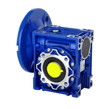
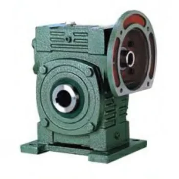
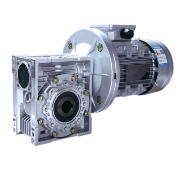
Product Description
Model:; XWSG7 electric operated part turn worm gearbox
| Model | Electric Output Torque N·m | Ratio | Electric Input Torque N·m | Input Flange ISO5210-2001 | Standard Base Output Flange | Thickened Base Output Flange | Max.; Stem Diameter mm | Input Shaft Diameter mm | APPROX.; Weight kg | ||||||||||||||
| XWSG4 | 1700 | 479 | 413 | 348 | 279 | 213 | 131 | 13 | 15 | 18 | 23 | 30 | 48 | F10/F12/F14 | N/A | F12/F14/F16 | 52 | 25 | 36 | ||||
| XWSG5 | 3000 | 472 | 407 | 343 | 275 | 210 | 129 | 24 | 27 | 32 | 40 | 53 | 86 | F10/F12/F14 | N/A | F14/F16/F25 | 76 | 25 | 62 | ||||
| XWSG6 | 7000 | 486 | 419 | 353 | 284 | 216 | 132 | 53 | 62 | 73 | 91 | 120 | 196 | F10/F12/F14 | N/A | F16/F25/F30 | 87 | 25 | 93 | ||||
| XWSG7 | 16000 | 566 | 485 | 420 | 359 | 310 | 251 | 181 | 113 | 105 | 122 | 141 | 165 | 191 | 236 | 327 | 523 | F10/F12/F14/F16 | F25/F30 | F25/F30/F35 | 120 | 35 | 167 |
| XWSG8 | 28000 | 566 | 485 | 420 | 359 | 310 | 251 | 181 | 113 | 183 | 214 | 247 | 289 | 335 | 413 | 573 | 914 | F10/F12/F14/F16 | F25/F30/F35 | F25/F30/F35/F40 | 153 | 35 | 276 |
| XWSG9 | 40000 | 566 | 485 | 420 | 359 | 310 | 251 | 181 | 113 | 262 | 306 | 353 | 412 | 479 | 589 | 818 | 1306 | F10/F12/F14/F16 | F30/F35 | F30/F35/F40/F48 | 170 | 35 | 343 |
| XWSG10 | 65000 | 771 | 711 | 659 | 612 | 561 | 483 | 419 | 367 | 312 | 339 | 365 | 393 | 429 | 498 | 575 | 656 | F16/F25 | F35/F40 | F35/F40/F48 | 190 | 45 | 755 |
| XWSG12 | 145000 | 771 | 711 | 659 | 612 | 561 | 483 | 419 | 367 | 697 | 755 | 815 | 878 | 957 | 1112 | 1282 | 1463 | F10/F14F16/F25 | F35/F40/F48 | F35/F40/F48/F60 | 220 | 45 | 1050 |
Introduction
XWS series part-turn worm gearbox is designed base on XW series,; and developed for large torque,; manual and automatic valve.; The first stage transmission of this series is using worm gear to drive,; second stage transmission is using worm gear or bevel gear to drive.; There are tapered roller bearings with high performance installed on both ends of the first stage worm shaft,; it can bear double-directional thrust while withstand radial forces,; and also the bearing clearance can be adjusted.; Therefore,; under large torque,; long life.;Because of the selectable double-stage input structure,; rotatable angle of mounting hole between output end cap and housing,; users can flexibly choose installation angle according to installation conditions.;
Characters
1.; Totally enclosed gearing with good sealing
2.; Ductile cast iron housing,; reliable strength
3.; Grease filled,; increase the service life
4.; Optional input structure,; flexible input mode
5.; Optional ratio of double-stage gearbox,; used in a wide range
6.; Adjustable angle of output end cap,; flexible modes of installation
7.; Optional output flange type
8.; High performance of tapered roller bearing,; can withstand axial and also radial forces
9.; Sealed structure,; good waterproof effect,; can be up to IP68 if required
10.; Adjustable stopper,; 0 °and 90 °(±5 °adjustable);
Application
XWS series part-turn worm gearbox is suitable for dampers,; ball valve,; butterfly valve and other 90 °rotary (quarter- turn); valves.;
Operating Environment
XWS series part-turn worm gearbox are with good mechanical quality and steady operating performance which apply to deal with variety climate and temperature.; We strive to develop RWS series worm gear operator to meet higher demands.;
Enclosure:; IP67 standard (Optional IP68 as required);
Working Temperature:; From -20ºC to 120ºC ( -4ºFto 248ºF);
Painting:; Silver grey (Customization);
Connect With Valve
The flange connecting to valve is according to ENISO5210 or DIN3210 (Customization);
Main Products
Worm gearbox,; bevel gearbox,; valve gear box,;worm gear operator,; worm gear actuator,; valve worm gear,; valve gear operator,; valve gear actuator,; valve actuator.;
Gear Operator,; Valve Gearbox,; Bevel Gearbox,; Gearbox,; Speed Reducer,; Multi-Turn Bevel Gearbox,; Bevel Gearbox Supplier,; High Quality Bevel Gearbox,; Gearbox manufacturer
| Application: | Industry |
|---|---|
| Type: | Worm and Wormwheel |
| Protection Level: | IP67 |
| Working Temperature: | -20 to 120 Degrees Celsius |
| Applications: | Ball Valves, Butterfly Valves, Plug Valves, Damper |
| Painting/Coating: | Silver Grey or Customization |
| Customization: |
Available
| Customized Request |
|---|

How to Install and Align a Worm Reducer Properly
Proper installation and alignment of a worm reducer are crucial for ensuring optimal performance and longevity. Follow these steps to install and align a worm reducer:
- Preparation: Gather all the necessary tools, equipment, and safety gear before starting the installation process.
- Positioning: Place the worm reducer in the desired location, ensuring that it is securely mounted to a stable surface. Use appropriate fasteners and mounting brackets as needed.
- Shaft Alignment: Check the alignment of the input and output shafts. Use precision measurement tools to ensure that the shafts are parallel and in line with each other.
- Base Plate Alignment: Align the base plate of the reducer with the foundation or mounting surface. Ensure that the base plate is level and properly aligned before securing it in place.
- Bolt Tightening: Gradually and evenly tighten the mounting bolts to the manufacturer’s specifications. This helps ensure proper contact between the reducer and the mounting surface.
- Check for Clearance: Verify that there is enough clearance for any rotating components or parts that may move during operation. Avoid any interference that could cause damage or performance issues.
- Lubrication: Apply the recommended lubricant to the worm reducer according to the manufacturer’s guidelines. Proper lubrication is essential for smooth operation and reducing friction.
- Alignment Testing: After installation, run the worm reducer briefly without a load to check for any unusual noises, vibrations, or misalignment issues.
- Load Testing: Gradually introduce the intended load to the worm reducer and monitor its performance. Ensure that the reducer operates smoothly and efficiently under the load conditions.
It’s important to refer to the manufacturer’s installation guidelines and specifications for your specific worm reducer model. Proper installation and alignment will contribute to the gearbox’s reliability, efficiency, and overall functionality.

How to Calculate the Efficiency of a Worm Gearbox
Calculating the efficiency of a worm gearbox involves determining the ratio of output power to input power. Efficiency is a measure of how well the gearbox converts input power into useful output power without losses. Here’s how to calculate it:
- Step 1: Measure Input Power: Measure the input power (Pin) using a power meter or other suitable measuring equipment.
- Step 2: Measure Output Power: Measure the output power (Pout) that the gearbox is delivering to the load.
- Step 3: Calculate Efficiency: Calculate the efficiency (η) using the formula: Efficiency (η) = (Output Power / Input Power) * 100%
For example, if the input power is 1000 watts and the output power is 850 watts, the efficiency would be (850 / 1000) * 100% = 85%.
It’s important to note that efficiencies can vary based on factors such as gear design, lubrication, wear, and load conditions. The calculated efficiency provides insight into how effectively the gearbox is converting power, but it’s always a good practice to refer to manufacturer specifications for gearbox efficiency ratings.

Preventing Backlash in a Worm Gearbox
Backlash in a worm gearbox can lead to reduced accuracy, positioning errors, and decreased overall efficiency. Here are steps to prevent or minimize backlash:
- High-Quality Components: Use high-quality worm gears and worm wheels with tight manufacturing tolerances. Precision components will help reduce backlash.
- Proper Meshing: Ensure the worm gear and worm wheel are properly aligned and meshed. Improper meshing can lead to increased backlash.
- Preload: Applying a small amount of preload to the worm gear can help reduce backlash. However, excessive preload can increase friction and wear.
- Anti-Backlash Mechanisms: Consider using anti-backlash mechanisms, such as spring-loaded systems or adjustable shims, to compensate for any inherent backlash.
- Lubrication: Proper lubrication can reduce friction and play a role in minimizing backlash. Use a lubricant that provides good film strength and reduces wear.
- Maintenance: Regularly inspect and maintain the gearbox to identify and address any changes in backlash over time.
It’s important to strike a balance between reducing backlash and maintaining smooth operation. Consulting with gearbox experts and following manufacturer guidelines will help you optimize your worm gearbox’s performance while minimizing backlash.


editor by CX 2024-01-15