Product Description
| Suitable for | Electronic door locks, smart switches, steam hair straighteners (water spray straight hair), label strippers, smart wear, smart machine 3D printing equipment products, hair curlers, safes, electric screwdrivers, display stands, etc. |
| Reduction ratio | 3.5.10.20.30.50.63.100.150.210.250.298.380.500.1000 |
| customizable | |
| Inspecation Equipment | Current and voltage tester.Speed tester. |
| Quality Control | 100% inspection |
| Customized | Yes, all are customized according clients’ drawings design or sample |
| Payment Way | T/T, Western Union, Paypal |
| Packaging | 1: Anti-rust oil OPP bags and cartons for outer packages. |
| 2: Customer’s requirement. | |
| Shipping | (1)0-100kg: Express & air freight priority |
| (2)>100kg: Sea freight priority | |
| (3)As per customized specifications. |
FAQ
Q: Are you a trading company or a factory?
A: We are factory&trading company. Our factory has been in operation for more than 30 years. We can offer you high quality products at a low price as soon as possible.
Q: What is the lead time and shipping time?
A: Common lead time is about 7-10days.
Q: Can the products be made with our logo or brand?
A: Yes of course we can make. We are OEM supplier for years and professional to make.
Q: My order quantity is small, can you provide?
Can be boxed according to product characteristics and customer requirementsA: No matter how many you want, we will service you nice and quickly.
Q: What is your Loading port?
A: Normally HangZhou.
*packaging
Can be boxed according to product characteristics and customer requirements
/* January 22, 2571 19:08:37 */!function(){function s(e,r){var a,o={};try{e&&e.split(“,”).forEach(function(e,t){e&&(a=e.match(/(.*?):(.*)$/))&&1
| Application: | Motor, Electric Cars, Machinery, Toy, Reducer |
|---|---|
| Function: | Change Drive Torque, Change Drive Direction, Speed Changing, Speed Reduction, Speed Increase, Reducer |
| Layout: | Customizable |
| Hardness: | Customizable |
| Installation: | Customizable |
| Step: | Customizable |
| Customization: |
Available
| Customized Request |
|---|

Self-Locking Properties in a Worm Gearbox
Yes, worm gearboxes exhibit self-locking properties, which can be advantageous in certain applications. Self-locking refers to the ability of a mechanism to prevent the transmission of motion from the output shaft back to the input shaft when the system is at rest. Worm gearboxes inherently possess self-locking properties due to the unique design of the worm gear and worm wheel.
The self-locking behavior arises from the angle of the helix on the worm shaft. In a properly designed worm gearbox, the helix angle of the worm is such that it creates a mechanical advantage that resists reverse motion. When the gearbox is not actively driven, the friction between the worm threads and the worm wheel teeth creates a locking effect.
This self-locking feature makes worm gearboxes particularly useful in applications where holding a load in position without external power is necessary. For instance, they are commonly used in situations where there’s a need to prevent a mechanism from backdriving, such as in conveyor systems, hoists, and jacks.
However, it’s important to note that while self-locking properties can be beneficial, they also introduce some challenges. The high friction between the worm gear and worm wheel during self-locking can lead to higher wear and heat generation. Additionally, the self-locking effect can reduce the efficiency of the gearbox when it’s actively transmitting motion.
When considering the use of a worm gearbox for a specific application, it’s crucial to carefully analyze the balance between self-locking capabilities and other performance factors to ensure optimal operation.

How to Calculate the Input and Output Speeds of a Worm Gearbox?
Calculating the input and output speeds of a worm gearbox involves understanding the gear ratio and the principles of gear reduction. Here’s how you can calculate these speeds:
- Input Speed: The input speed (N1) is the speed of the driving gear, which is the worm gear in this case. It is usually provided by the manufacturer or can be measured directly.
- Output Speed: The output speed (N2) is the speed of the driven gear, which is the worm wheel. To calculate the output speed, use the formula:
N2 = N1 / (Z1 * i)
Where:
N2 = Output speed (rpm)
N1 = Input speed (rpm)
Z1 = Number of teeth on the worm gear
i = Gear ratio (ratio of the number of teeth on the worm gear to the number of threads on the worm)
It’s important to note that worm gearboxes are designed for gear reduction, which means that the output speed is lower than the input speed. Additionally, the efficiency of the gearbox, friction, and other factors can affect the actual output speed. Calculating the input and output speeds is crucial for understanding the performance and capabilities of the worm gearbox in a specific application.

Types of Worm Gear Configurations and Their Uses
Worm gear configurations vary based on the arrangement of the worm and the gear it engages with. Here are common types and their applications:
- Single Enveloping Worm Gear: This configuration offers high torque transmission and efficiency. It’s used in heavy-duty applications like mining equipment and industrial machinery.
- Double Enveloping Worm Gear: With increased contact area, this type provides higher load capacity and improved efficiency. It’s used in aerospace applications, robotics, and precision machinery.
- Non-Throated Worm Gear: This type has a cylindrical worm without a throat. It’s suitable for applications requiring precise motion control, such as CNC machines and robotics.
- Throated Worm Gear: Featuring a throat in the worm, this configuration offers smooth engagement and higher load capacity. It’s used in conveyors, elevators, and automotive applications.
- Non-Modular Worm Gear: In this design, the worm and gear are a matched set, resulting in better meshing and efficiency. It’s utilized in various industries where customization is essential.
- Modular Worm Gear: This type allows interchangeability of worm and gear components, providing flexibility in design and maintenance. It’s commonly used in conveyors, mixers, and material handling systems.
Selecting the appropriate worm gear configuration depends on factors such as load capacity, efficiency, precision, and application requirements. Consulting gearbox experts can help determine the best configuration for your specific needs.


editor by CX 2024-04-22
China OEM Nmrv Transmission Aluminum Alloy Worm Gear Gearbox Economic, Micro Worm Gear Box gearbox and motor
Product Description
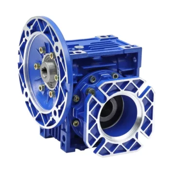
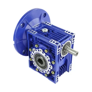
SMRV series worm-gear speed reducer is a new-generation of products developed by our company with combination of advanced by technology both at home and abroad.
Characteristics
(1)Large output torque
(2) Safe, reliable, economical and durable
(3) Stable transmission, quiet operation
(4) High heat-radiating efficiency, high carrying ability
(5) Combination of 2 single-step worm gear speed reducers, meeting the requirements of super speed ratio
(6) Mechanical gearboxes are widely used in the sectors,like foodstuff, ceramics, and chemical manufacturing, as well as packing, printing, dyeing and plastics
Technical data
(1) Motor input power:0.06kw-15kw
(2) Output torque:4-2320N.M
(3) Speed ratio of worm gear peed reducer: 5/10/15/20/25/30/40/50/60/80/100
(4) With IEC motor input flange: 56B14/71B14/80B5/90B5
Materials
(1) NMRV571-NMRV090: Aluminium alloy housing
(2) NMRV110-150: Cast iron housing
(3) Bearing: CHINAMFG bearing & Homemade bearing
(4) Lubricant: Synthetic & Mineral
(5) The material of the worm mandrel is HT250, and the worm ring gear is ZQSn10-1.
(6) With high quality homemade bearings, assembled CHINAMFG oil seals & filled with high quality lubricant.
Operation&mantenance
(1)When worm speed reducer starts to work up to200-400 hours, its lubricant should be replaced.
(2)The gearbox need to replace the oil after 4000 hours.
(3)Worm reduction gearbox is fully filled with lubricant oil after finshed assembly.
(4)Lubricanting oil should be kept enough in the casing and checked at a fixed time.
Color
(1) Blue / Light blue
(2) Silvery White
Quality control
(1) Quality guarantee: 1 year
(2) Certificate of quality: ISO9001:2000
(3) Every product must be tested before sending
| Motor power | Model | speed ratio | output speed | output toruqe |
| 0.06kw 1400rpm | NMRV030 | 5 | 280rpm | 2.0N.M |
| NMRV030 | 7.5 | 186rpm | 2.6N.M | |
| NMRV030 | 10 | 140rpm | 3.3N.M | |
| NMRV030 | 15 | 94rpm | 4.7N.M | |
| NMRV030 | 20 | 70rpm | 5.9N.M | |
| NMRV030 | 25 | 56rpm | 6.8N.M | |
| NMRV030 | 30 | 47rpm | 7.9N.M | |
| NMRV030 | 40 | 35rpm | 9.7N.M | |
| NMRV030 | 50 | 28rpm | 11.0N.M | |
| NMRV030 | 60 | 24rpm | 12.0N.M | |
| NMRV030 | 80 | 18rpm | 14.0N.M | |
| 0.09kw 1400rpm | NMRV030 | 5 | 280rpm | 2.7N.M |
| NMRV030 | 7.5 | 186rpm | 3.9N.M | |
| NMRV030 | 10 | 140rpm | 5.0N.M | |
| NMRV030 | 15 | 94rpm | 7.0N.M | |
| NMRV030 | 20 | 70rpm | 8.8N.M | |
| NMRV030 | 25 | 56rpm | 10.0N.M | |
| NMRV030 | 30 | 47rpm | 12.0N.M | |
| NMRV030 | 40 | 35rpm | 14.0N.M | |
| NMRV030 | 50 | 28rpm | 17.0N.M | |
| NMRV030 | 60 | 24rpm | 18.0N.M | |
| 0.12kw 1400rpm | NMRV030 | 5 | 280rpm | 3.6N.M |
| NMRV030 | 7.5 | 186rpm | 5.2N.M | |
| NMRV030 | 10 | 140rpm | 6.6N.M | |
| NMRV030 | 15 | 94rpm | 9.3N.M | |
| NMRV030 | 20 | 70rpm | 12.0N.M | |
| NMRV030 | 25 | 56rpm | 14.0N.M | |
| NMRV030 | 30 | 47rpm | 16.0N.M | |
| NMRV030 | 40 | 35rpm | 19.0N.M | |
| NMRV030 | 50 | 28rpm | 22.0N.M | |
| 0.18kw 1400rpm | NMRV030 | 5 | 280rpm | 5.3N.M |
| NMRV030 | 7.5 | 186rpm | 7.7N.M | |
| NMRV030 | 10 | 140rpm | 10.0N.M | |
| NMRV030 | 15 | 94rpm | 14.0N.M | |
| NMRV030 | 20 | 70rpm | 18.0N.M | |
| NMRV030 | 25 | 56rpm | 20.0N.M | |
| NMRV030 | 30 | 47rpm | 24.0N.M |
|
Shipping Cost:
Estimated freight per unit. |
To be negotiated |
|---|
| Application: | Machinery, Industry |
|---|---|
| Function: | Speed Reduction |
| Layout: | Coaxial |
| Samples: |
US$ 23/Piece
1 Piece(Min.Order) | Order Sample |
|---|
| Customization: |
Available
| Customized Request |
|---|

Calculating Gear Ratio in a Worm Reducer
The gear ratio in a worm reducer is determined by the number of teeth on the worm wheel (also known as the worm gear) and the number of threads on the worm shaft. The gear ratio formula for a worm reducer is:
Gear Ratio = Number of Teeth on Worm Wheel / Number of Threads on Worm Shaft
For example, if the worm wheel has 60 teeth and the worm shaft has a single thread, the gear ratio would be 60:1.
It’s important to note that worm reducers have an inherent self-locking property due to the angle of the worm threads. As a result, the gear ratio also affects the mechanical advantage and the system’s ability to resist backdriving.
When calculating the gear ratio, ensure that the worm reducer is properly designed and that the gear ratio aligns with the desired mechanical characteristics for your application. Additionally, consider factors such as efficiency, load capacity, and speed limitations when selecting a gear ratio for a worm reducer.

How to Calculate the Input and Output Speeds of a Worm Gearbox?
Calculating the input and output speeds of a worm gearbox involves understanding the gear ratio and the principles of gear reduction. Here’s how you can calculate these speeds:
- Input Speed: The input speed (N1) is the speed of the driving gear, which is the worm gear in this case. It is usually provided by the manufacturer or can be measured directly.
- Output Speed: The output speed (N2) is the speed of the driven gear, which is the worm wheel. To calculate the output speed, use the formula:
N2 = N1 / (Z1 * i)
Where:
N2 = Output speed (rpm)
N1 = Input speed (rpm)
Z1 = Number of teeth on the worm gear
i = Gear ratio (ratio of the number of teeth on the worm gear to the number of threads on the worm)
It’s important to note that worm gearboxes are designed for gear reduction, which means that the output speed is lower than the input speed. Additionally, the efficiency of the gearbox, friction, and other factors can affect the actual output speed. Calculating the input and output speeds is crucial for understanding the performance and capabilities of the worm gearbox in a specific application.

Advantages of Using a Worm Reducer in Mechanical Systems
Worm reducers offer several advantages that make them suitable for various mechanical systems:
- High Gear Reduction Ratio: Worm gearboxes provide significant speed reduction, making them ideal for applications that require a high gear reduction ratio without the need for multiple gears.
- Compact Design: Worm reducers have a compact and space-saving design, allowing them to be used in applications with limited space.
- Self-Locking: Worm gearboxes exhibit self-locking properties, which means that the worm screw can prevent the worm wheel from reversing its motion. This is beneficial for applications where the gearbox needs to hold a load in place without external braking mechanisms.
- Smooth and Quiet Operation: Worm gearboxes operate with a sliding motion between the teeth, resulting in smoother and quieter operation compared to some other types of gearboxes.
- High Torque Transmission: Worm gearboxes can transmit high torque levels, making them suitable for applications that require powerful torque output.
- Heat Dissipation: The sliding action between the worm screw and the worm wheel contributes to heat dissipation, which can be advantageous in applications that generate heat during operation.
- Stable Performance: Worm reducers offer stable and reliable performance, making them suitable for continuous operation in various industrial and mechanical systems.
Despite these advantages, it’s important to note that worm gearboxes also have limitations, such as lower efficiency compared to other gear types due to the sliding motion and potential for higher heat generation. Therefore, selecting the appropriate type of gearbox depends on the specific requirements and constraints of the application.


editor by CX 2023-09-28